COMAP - INSTRUMENT
Pathfinder Instrument
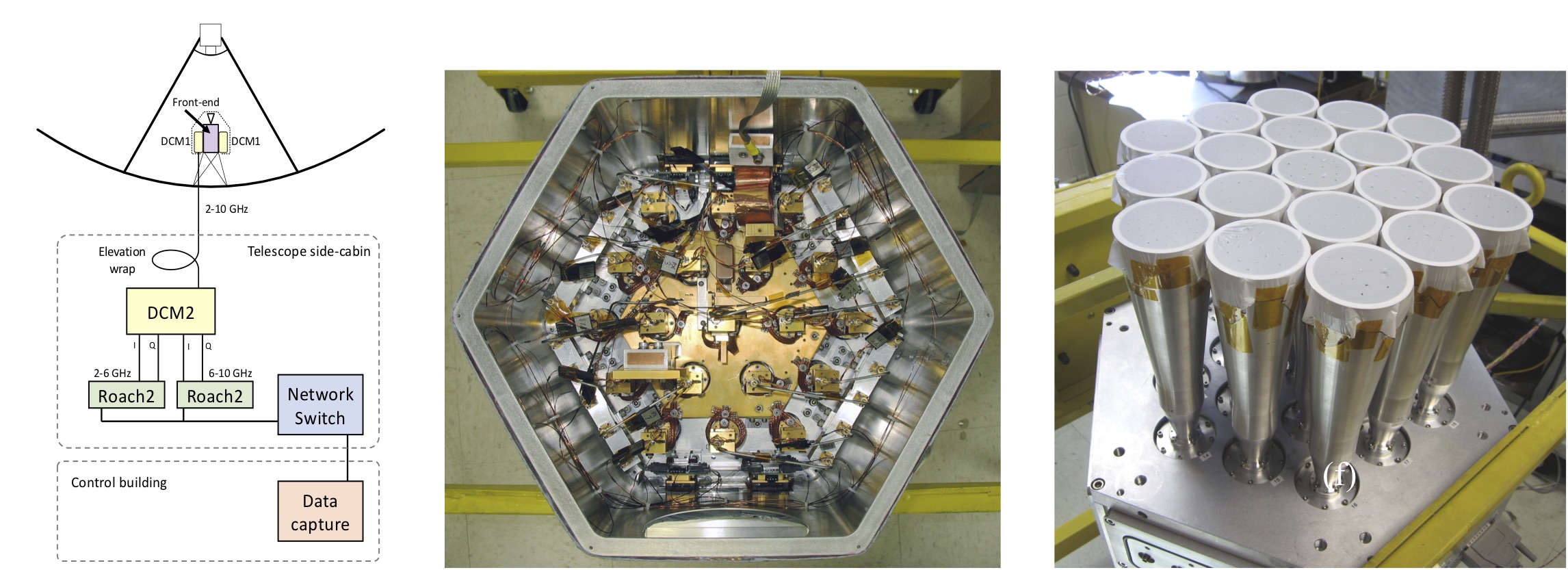
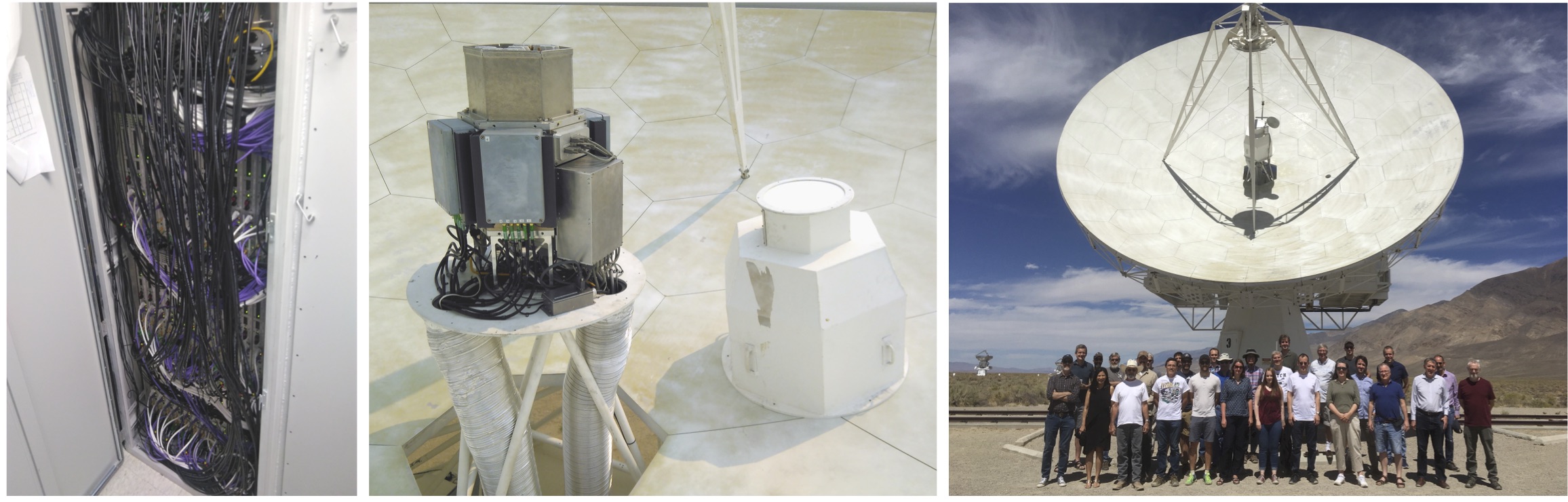
The COMAP Pathfinder targets the 26–34 GHz frequency range, which is sensitive to the CO(1-0) line in the redshift range z=2.4–3.4 and the CO(2-1) line at z=5.8–7.9. The Pathfinder receiver is a single-polarization 19-pixel focal plane array, deployed on a 10.4-m Leighton telescope at the Owens Valley Radio Observatory (OVRO). The first downconversion stage shifts the 26–34 GHz band to 2–10 GHz in modules mounted on the cryostat exterior (see block diagram above). The second downconversion stage occurs inside the telescope side-cabin, where the 2–10 GHz band from each pixel is split into two 4 GHz bands, each of which is quadrature downconverted to produce an “in-phase” (I) and “quadrature” (Q) signal.
Each IQ pair is input to a CASPER “Roach2” FPGA-based spectrometer. Custom FPGA code in each Roach2 performs sideband separation, resulting in four 2-GHz wide sidebands from each pixel, each of which has 1024 spectral channels (i.e. ∼ 2 MHz spectral resolution). In order to process all 8 GHz bandwidth from each of 19 pixels, 38 “Roach2” spectrometers are needed. Spectra are recorded every 20 ms and sent via Ethernet to a storage machine in a nearby control building. From there, these data are transmitted to Caltech campus via internet and stored on two 288 TB machines. The spectra are then combined with pointing and housekeeping data and are available for further analysis and processing.
Low Noise Amplifiers
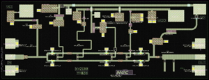
The COMAP receiver is based on cooled Indium Phosphide low noise amplifiers (LNA) designed to cover the 26-34 GHz band. These amplifiers are monolithic microwave integrated circuits (MMIC), each incorporating six individual high electron-mobility transistors (HEMT).